Data Preparation
There are many 3D formats, therefore the first step is to convert the 3D data into supported formats by the web application. In the folowing section, the detailed instructions on how to preprocess the data in selected softwares (namely in ArcGIS Pro, Blender and SketchUp) before uploading it to the application.
Coordinate System of GIS vs. 3D Graphics Software
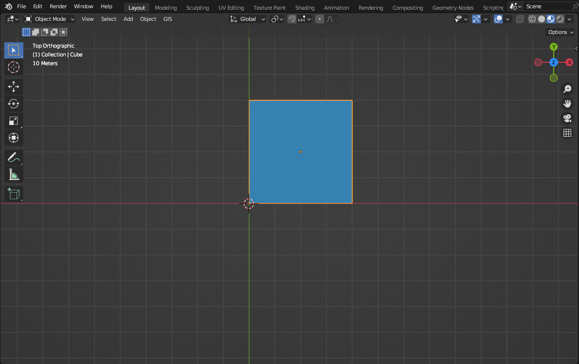
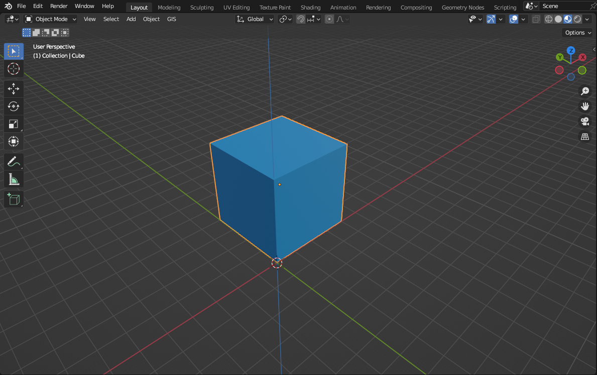
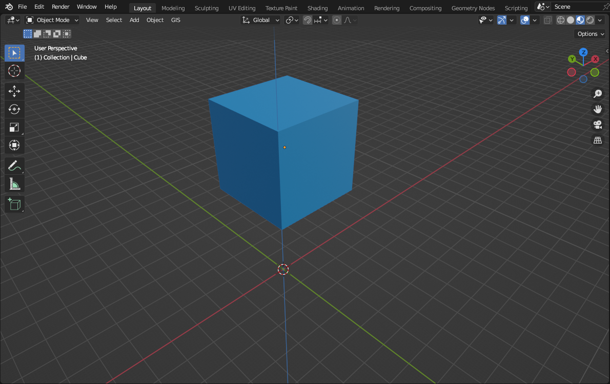
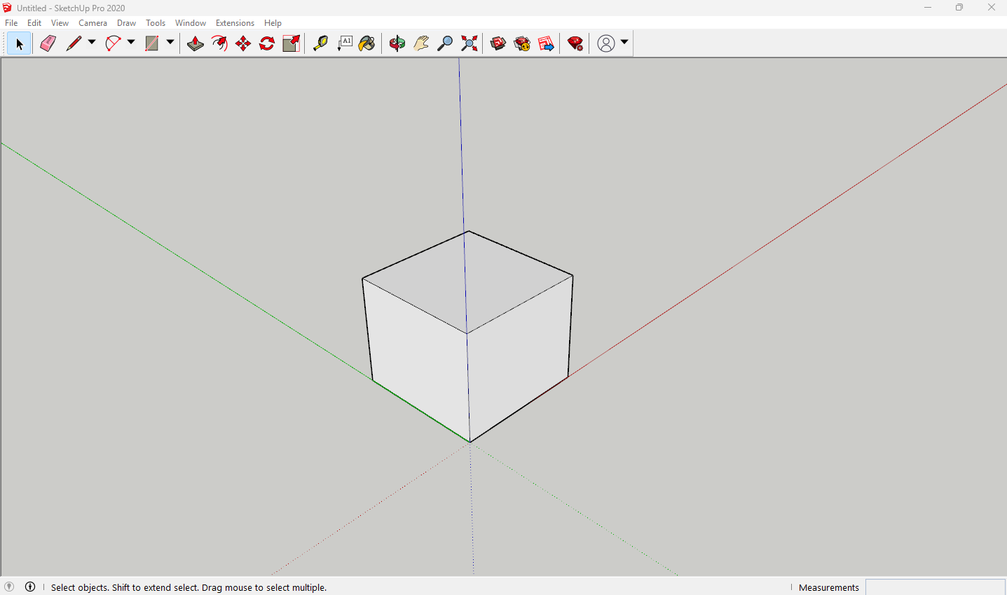
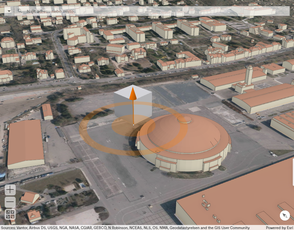
Firstly, it is important to understand how the model is placed into the web scene. Just for the illustration, we will use the software Blender. Here we made a simple cube with a 40 m long edge (you can download it here). The placement of the object is always tied to the origin of the coordinate system. It is the point with coordinates 0, 0, 0 – X (red axis), Y (green axis) a Z (blue axis) – we will call this point as a reference point (Pic. 1, Pic. 2).
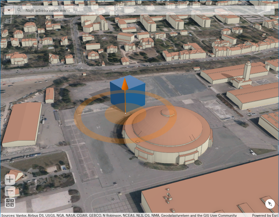
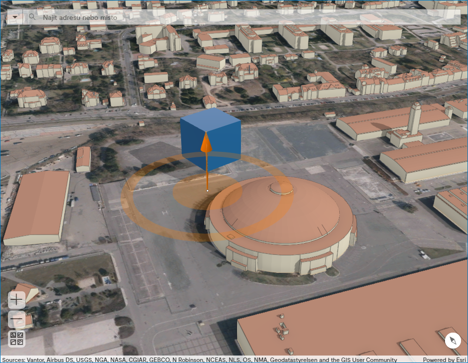
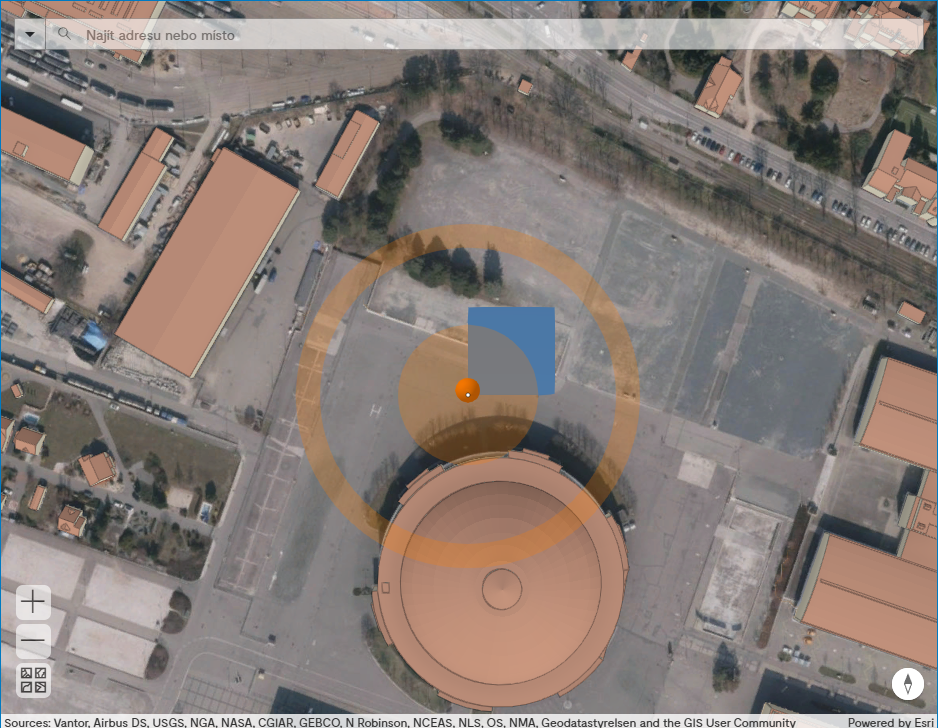
The reference point is considered as the snap point of the model in the application, after the export from Blender into the .glb file and uploading into the application. The snap point is a midpoint of the orange circle marked with a white dot (Pic. 3). When we move the model by a cursor in the scene or enter the exact coordinates, all these operations are performed in the relation to the snap point.
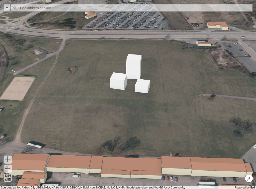
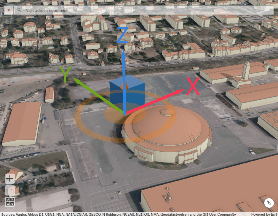
Let’s move the cube in Blender 20 m higher along the Z axis (Pic. 4) and upload again the model into the web application. We can see now, that the cube does not lie on the terrain but hovers 20 m above it (Pic. 5).
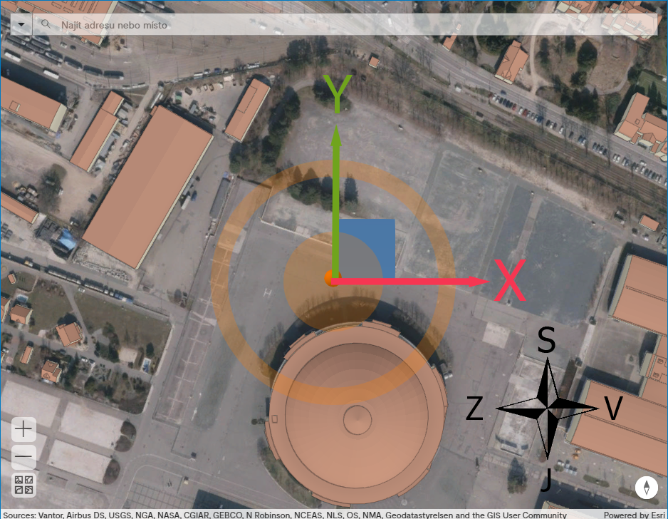
The orientation of the axis Y is from the south to the north and the axis X from the west to the east (Pic. 6). The axis Z runs from the bottom to the top and defines the altitude of the model (Pic. 7).
Neither Blender, nor SkecthUp works with the spatial reference systems, so the same principles apply to SkecthUp and most other 3D graphics software.
Model Preparation
The difference between the model and the project can be found in the subsection Model vs. Project.
ArcGIS Pro
Import
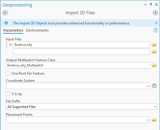
If you don’t have a 3D file in the format of multipatch, you need to convert it before moving to the next step. ArcGIS Pro can perform the conversion from various formats.
The file must be in the appropriate coordinate system used by the web application which is WGS84 with WKID: 4326. When the model is not defined in this system, it must be converted before the import using the ArcGIS tool Project.
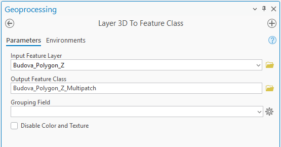
Polygon Z
If the model is created using a polygon with a Z-coordinate, it should be converted into multipatch using the tool Layer 3D To Feature Class (3D Analyst).
This tool is only available with the extension 3D Analyst
IFC, DWG
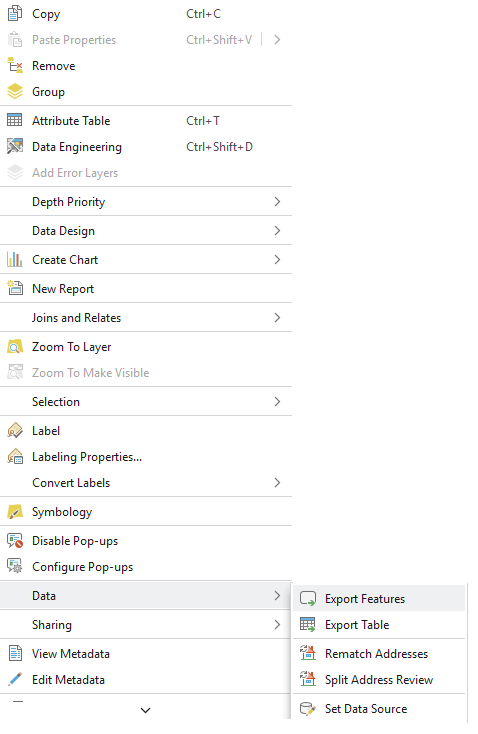
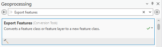
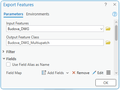
There are two ways to convert from IFC and .dwg into multipatch. Either right click on the layer in the Content and choose Data and then Export Features (Pic. 9), or type in the search bar of the geoprocessing pane (Pic. 10) Export Features (Pic. 11).
Other 3D files
Supported file formats are also: 3D Studio Max (.3ds), VRML and GeoVRML (.wrl), OpenFlight (.flt), COLLADA (.dae), and Wavefront OBJ models (.obj)
Use the tool Import 3D Files for the conversion into multipatch from the above mentioned supported formats.
This tool is only available with the extension 3D Analyst
Export
Conversion of the Multipatch into .glb File Format
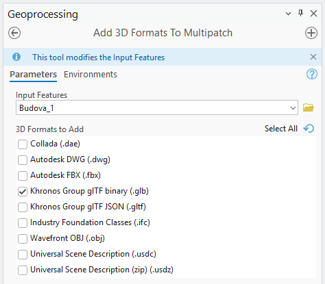
Firstly, add the right format to multipatch using the tool Add 3D Formats To Multipatch (Pic. 13). Choose the Khronos Group glTF binary (.glb) from the available formats.
Export .glb file
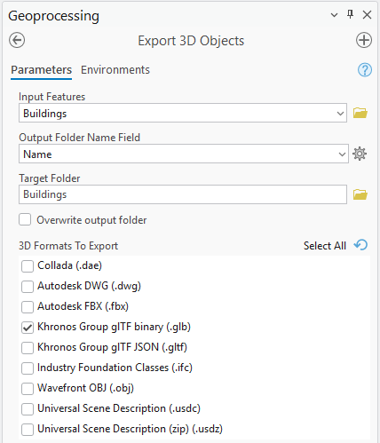
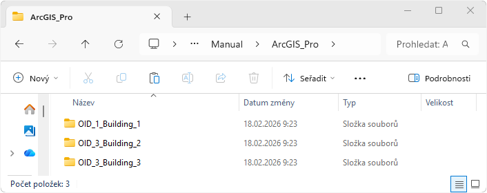
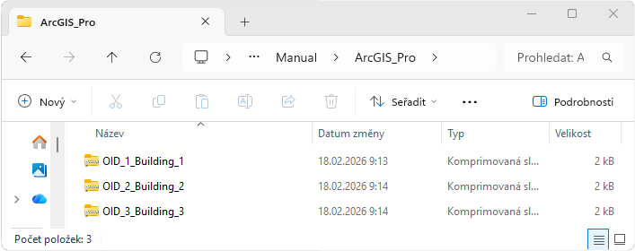
Export then the .glb file with the tool Export 3D Objects (Pic. 14). You can choose in an optional parameter Output Folder Name Field the column, which contains the names of our models when you need to split the model into more parts. The names are reflected in the foldernames e.g. OID_1_Building_1, where OID_1 is a unique name automatically generated by the tool and Building_1 is a string transfered from the chosen field (in our example below: Name).
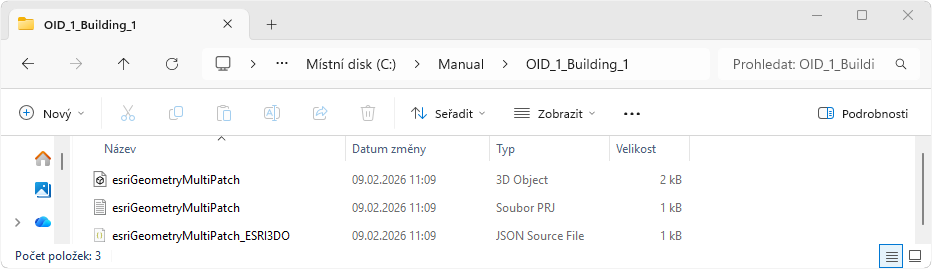
For every model a new folder is created with the following structure (Pic. 15): .glb (the model itself), .prj (the definition of the spatial coordinate system) and JSON (the metadata description of the model for ArcGIS Pro – the most important is the position of the reference point).
Blender
Blender, as well as SketchUp described in the following subsection, does not cope with the spatial coordinate systems, therefore the model must be always placed in relation to the origin (read more in Coordinate System of GIS vs. 3D Graphics Software). We recommend you this youtube channel Blender 3D Architect if you want to learn more about using Blender for architects.
Blender version 5.0 is used in the instructions – there might be some deviations in other versions.

Import
It is highly recommended not to place the model in the coordinates of any spatial reference system (like S-JTSK or WGS84) when we create the model out of Blender. Altough the model will load into Blender, it will be placed far from the origin and thus any subsequent work with it will be at least uncomfortable. Moving the model to the Blender’s origin will be even more complicated.
The version of Blender affects which file formats are natively supported. You can see the supported file formats in the version 5.0 in Pic. 17.
Albeit you cannot import all conceivable formats into Blender by default, there are many plugins which cover many others. For example this video shows how to import a .dwg file.
Export
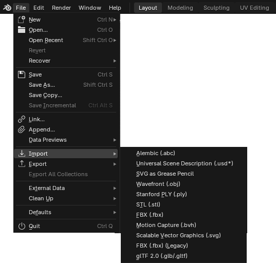
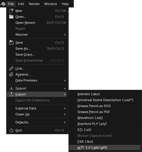
You can upload the model into the web application only in the supported .glb format, which can be easily done natively in Blender (unlike SketchUp) by clicking File > Export > glTF 2.0 (.glb/.gltf).
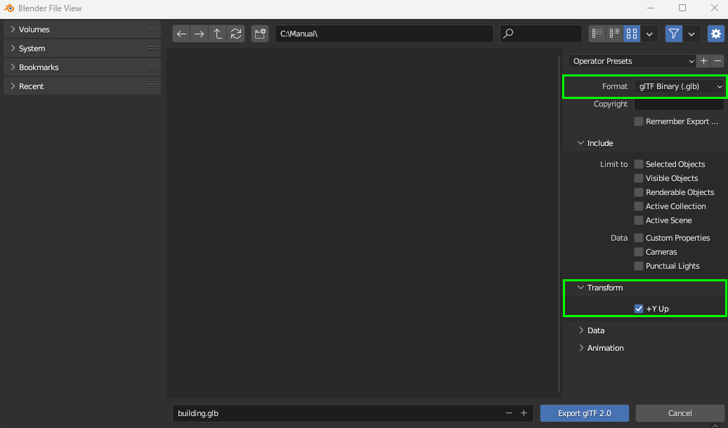
A new window shows up where you can leave everything unchanged. Just make sure, that Format is set to the glTF Binary (.glb) and the option +Y Up is checked in the section Transform (Pic. 19).
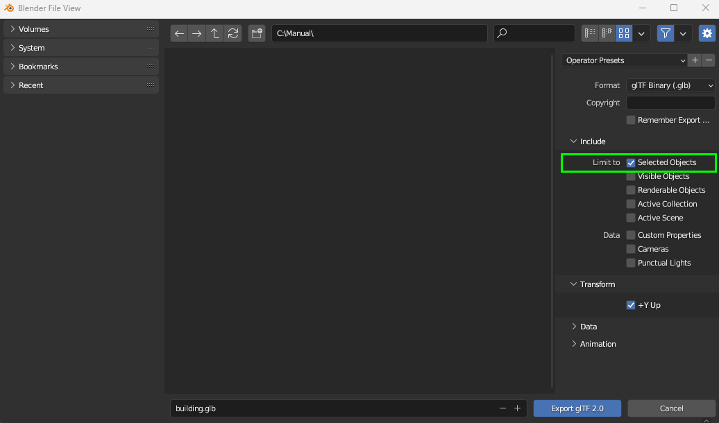
When you have more objects in Blender, it is recommended to choose only the model which you want to export. Then, when you export it, you check the Limit to – Selected Objects in the section Include (Pic. 20).
SketchUp
SketchUp, as well as Blender described in the previous subsection, does not cope with the spatial coordinate systems, therefore the model must be always placed in the relation to the origin (read more in Coordinate System of GIS vs. 3D Graphics Software).
Export
SketchUp does not support the .glb file format by deafult, therefore install the extension SketchUp glTF Exporter.
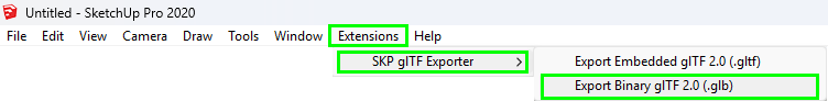
After the download and installation of the extension go to Extension → SKP gLTF Exporter → Export Binary glTF 2.0 (.glb). Be careful to choose .glb, not .gltf.
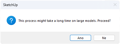
You are warn of possible long time needed for the import before the process starts. It depends on the size of the model.
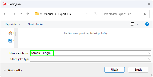
The Save As window appears. Here type in the filename as well as the file extension .glb (Pic. 27).
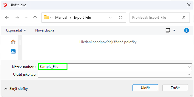
If you omit the file extension (Pic. 28), you will not be able to upload the model into the web application.
Project Preparation
Webová aplikace
The model can be exported into the project using the web applicartion. The corresponding instructions can be found in the section Export to Project.
ArcGIS Pro
The project can be created in the ArcGIS Pro as well. Firstly, you need to create the model in .glb. Then continue below.
Creation of ZIP archive → Project
See the folder with the created files (Pic. 30).
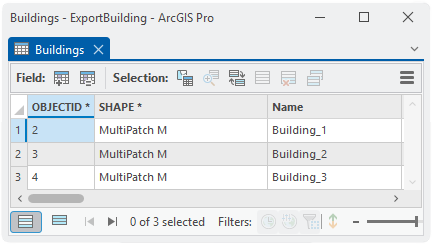
Three subfolders were created in our example because the model comprises three parts. The number of parts that model is composed of can be found in the attribute table of its layer (Pic. 31).
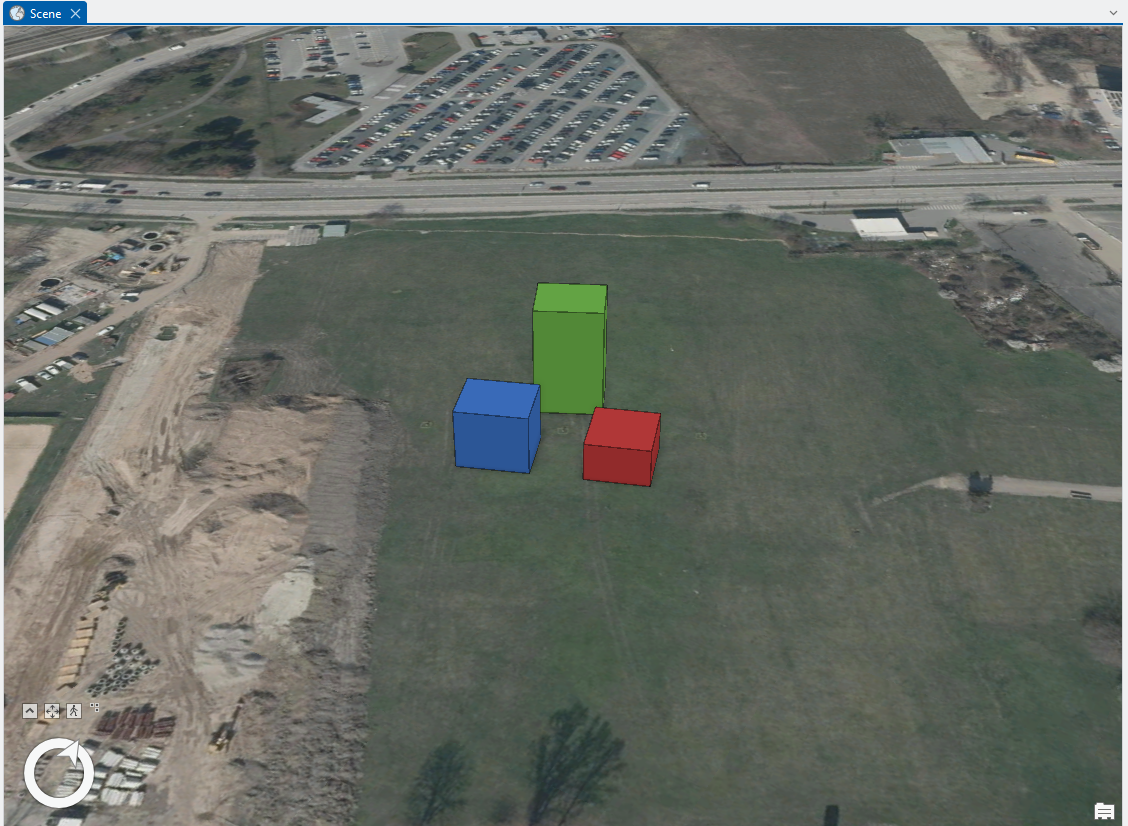
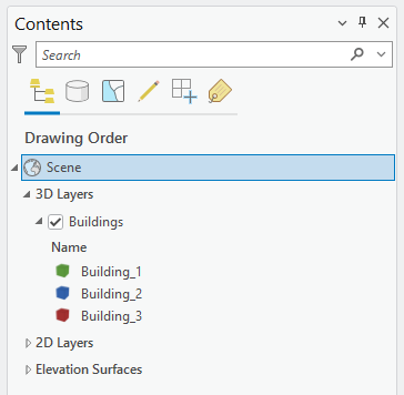
The rule says: the number of elements in the attribute table equals the number of parts into which our model is divided and that equals the number of the projects as well. To illustrate it even more clearly, we set different colour to each element (Pic. 32, Pic. 33).
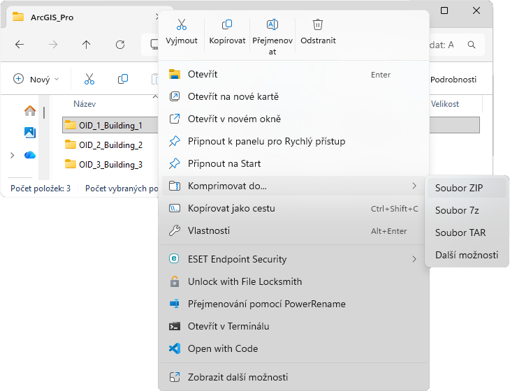
Each folder needs to be compressed into ZIP (Pic. 34) which is the only supported format for the project by the web application. All previously created folders must be compressed (Pic. 35).
Each file (ZIP archives = projects) can be gradually read into the web application and placed automatically on the right coordinates as the project.